4. Chassis Assembly
This section will guide the operator through the step-by-step process of assembling the main trap chassis, which forms the structural core of the T.R.A.P. system.
4.1 Parts List
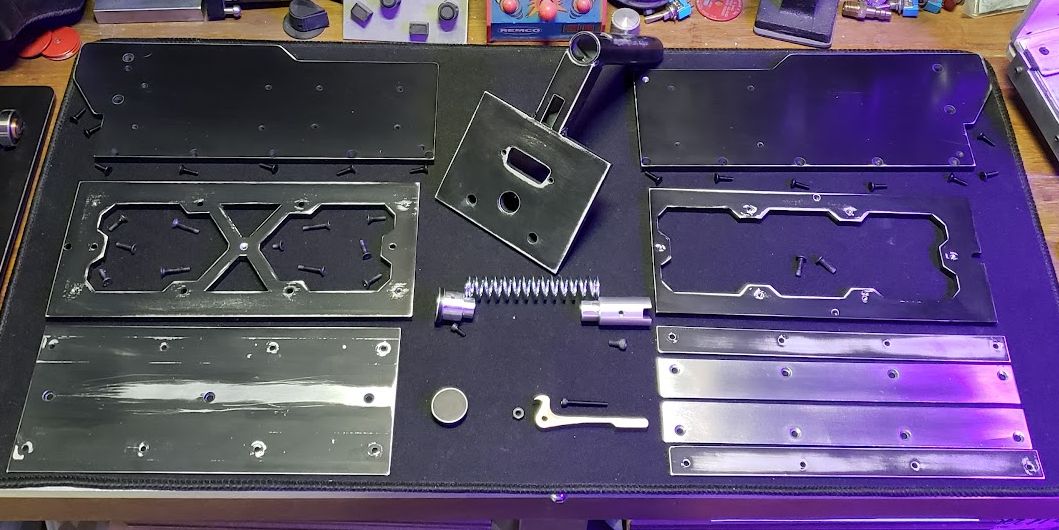
Before you begin, ensure you have the following components and complaints are prep:
- Universal Mounting Plate (2x Socket Button Head #6-32 x 7/16”)
- Chassis Base
- Chassis Track Base (1x Flat Head #4-40 x 1/4” and 2x Flat Head #4-40 x 1/2”)
- Chassis Track Guides (4x Flat Head 4-40 x 7/16” and 4x Flat Head 4-40 x 5/8”)
- Right Wall (5x Flat Head 4-40 x 7/16”)
- Left Wall (5x Flat Head 4-40 x 7/16”)
- Rear Wall Assembly (4x Flat Head #4-40 x 7/16” and 1x Socket Cap #4-40 x 1/4”)
- Release Lever (1x Socket Cap #4-40 x 7/8” and 1x Nut #4-40”)
- Lock (1x Spring and 1x Socket Cap #6-32 x 1/4”)
- Rear Handle Cap (4x Flat Head 4-40 x 1/4”)
- Front Handle Cap
Tool Bits:
- 1/16" hex bit
- 5/64" hex bit
- 3/32" hex bit
- 7/64" hex bit
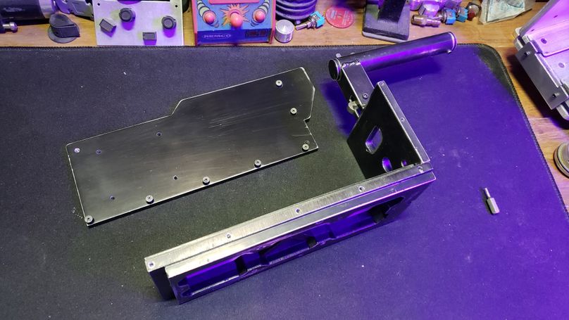
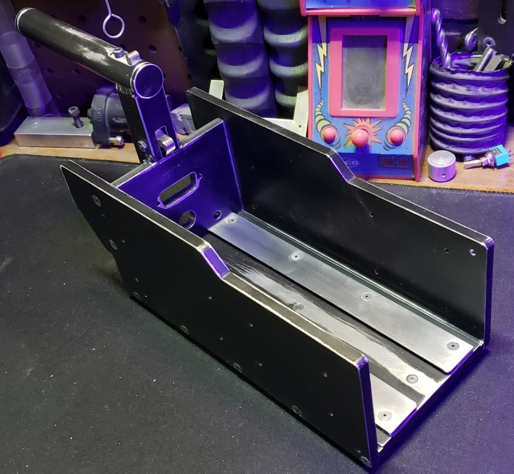
4.2 Assembly of the Chassis Base and Track Guides
Base Plate Orientation and Fastening:
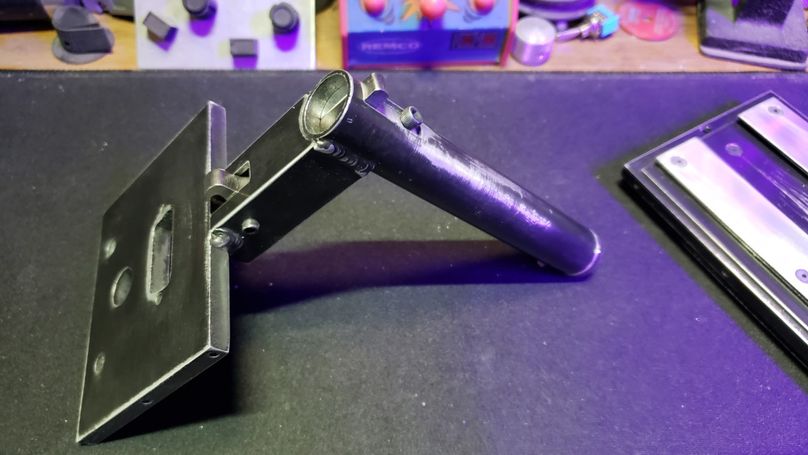
Lay the Chassis Base on top of the Universal Mounting Plate.
Crucial Orientation: Ensure correct part orientation. The single hole closest to the edge on the Chassis Base indicates the rear and must align with the U-shaped notch at the back of the Universal Mounting Plate.
Next, place the Chassis Track Base on top of the Chassis Base. This plate's orientation is also critical; when aligned correctly, it will sit flush with the front edge of the Chassis Base.
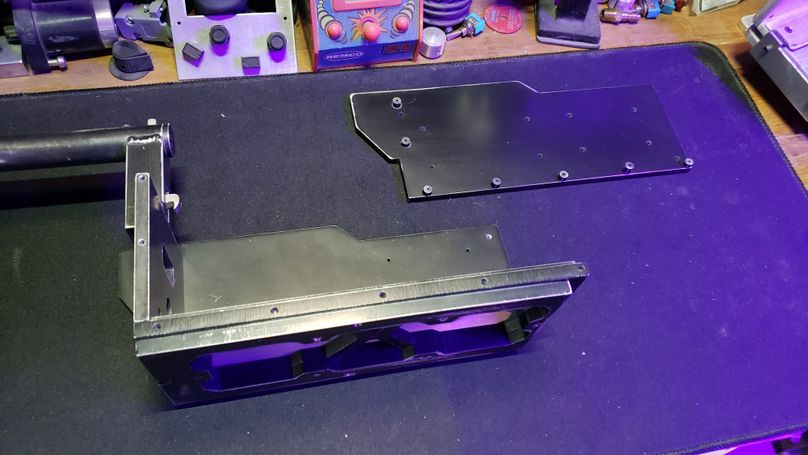
Securing the Base Layers:
Secure the stacked layers (Chassis Track Base / Chassis Base / Universal Mounting Plate) together using the three center screws.
Use the 1x Flat Head #4-40 x 1/4” screw in the center hole.
Use the 2x Flat Head #4-40 x 1/2” screws on the sides (one per side).
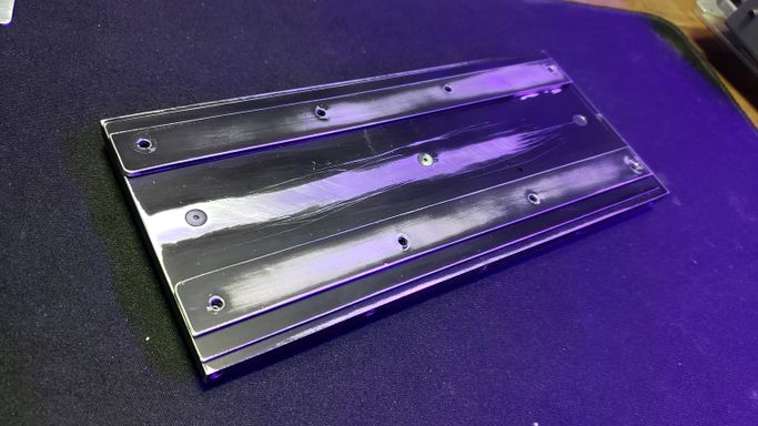
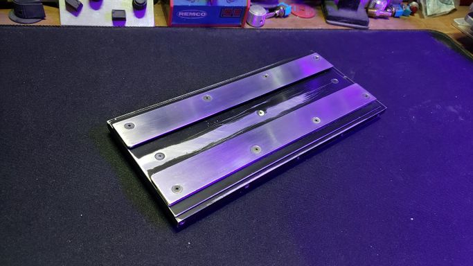
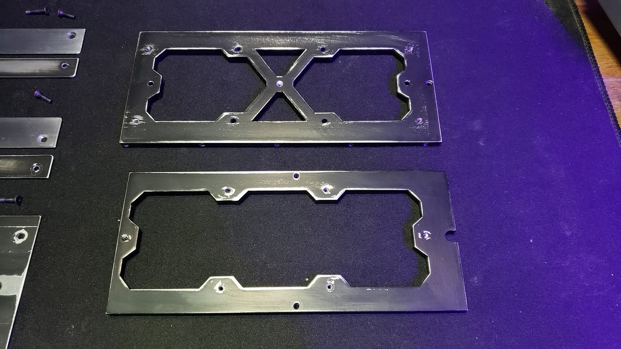
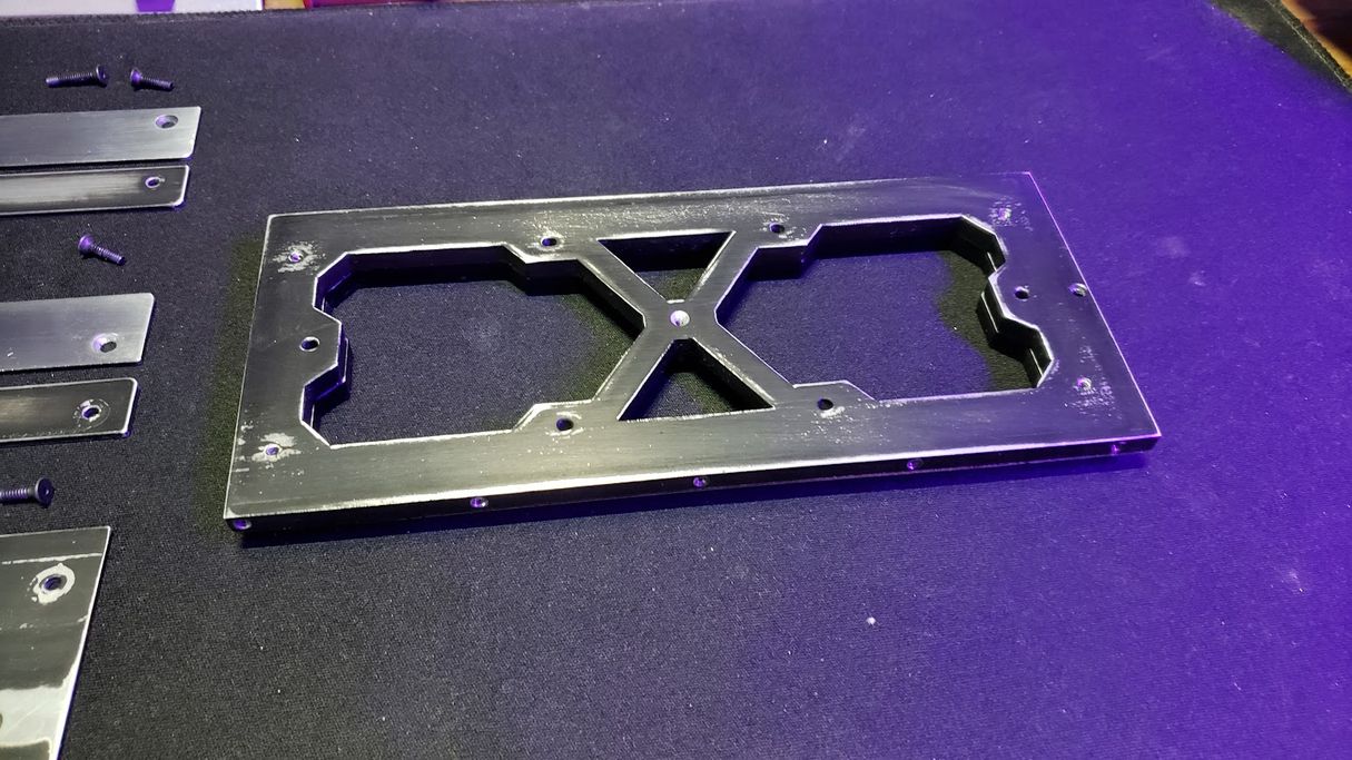
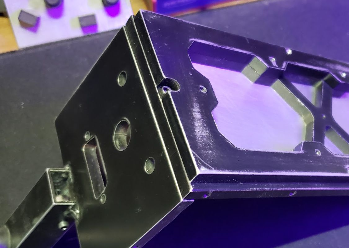
Installing the Track Guides:
The Chassis Track Guides are installed in two layers. The middle (smaller track) goes on first, then the larger track goes on top of it.
Orientation is Critical: Both sets of track guides have a radius (rounded edge) on one side. This radius must be positioned at the front of the trap and point inwards toward the center of the chassis.
The track guides are mounted to the Chassis Base using the following fasteners:
Use 2x #4-40 x 5/8” Flat Head screws for the middle track holes.
Use 2x #4-40 x 7/16” Flat Head screws for the outer track holes.
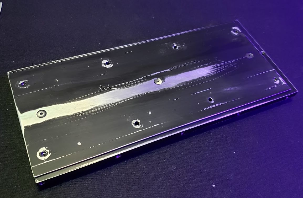
Flush Fitting (Important Note):
All Flat Head screws used in this base assembly must sit flush or slightly below the surface of the Chassis Track Base.
If a Flat Head screw does not sit at least flush, it is recommended to leave the other screws in place and use a countersink bit on the hole to achieve a flush fitting (refer to Section 3.2 for Countersinking procedure).
4.3 Assembly of the Rear Handle Wall and Cartridge Release Lever
This section focuses on assembling the Rear Wall/Handle components & Integrating the Cartridge Release Lever and Lock mechanism.
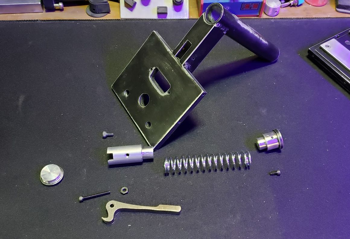
Release Lever Assembly:
Before mounting the Rear Wall, assemble the Release Lever mechanism.
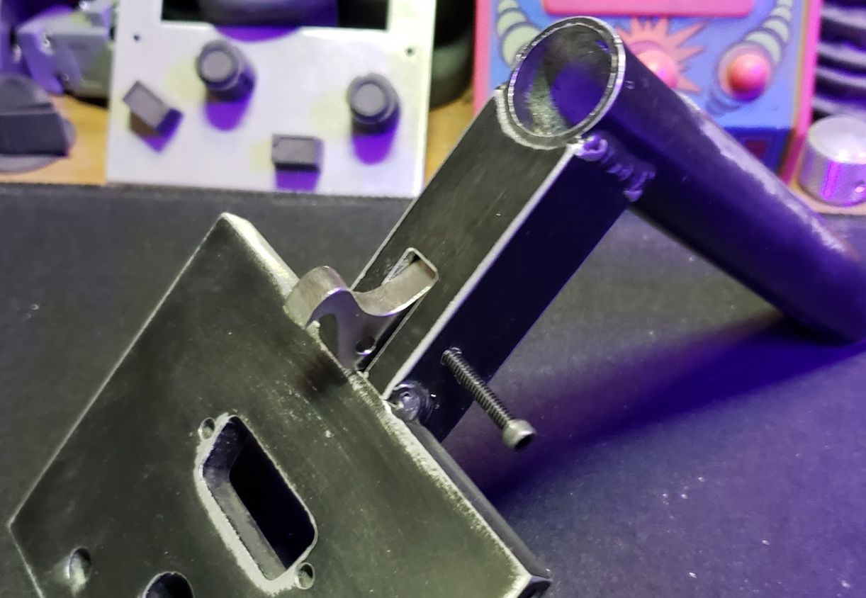
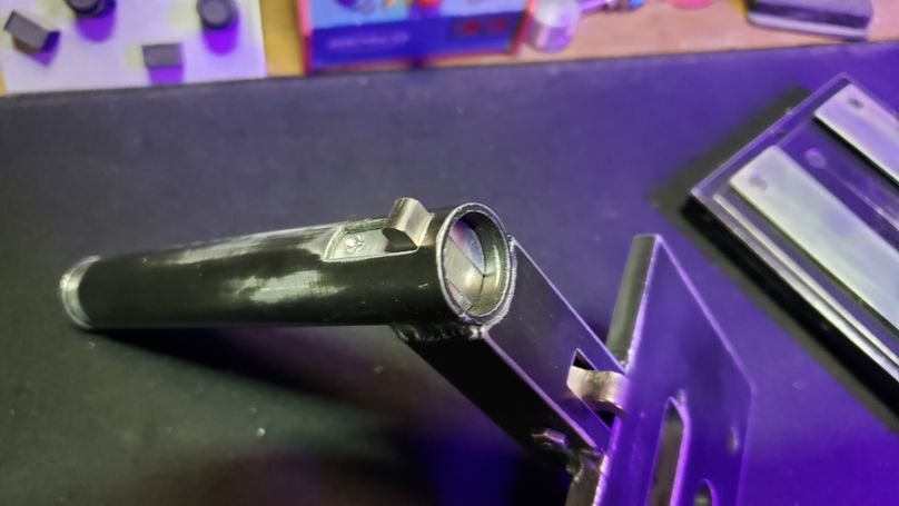
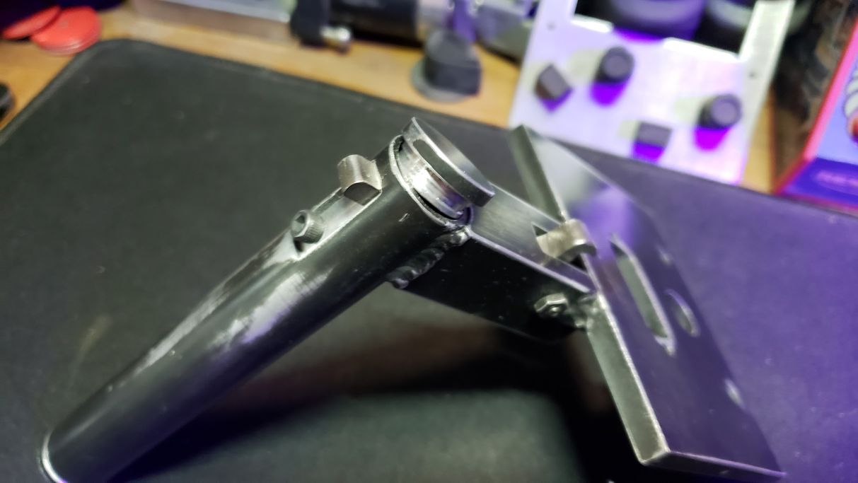
Take the Release Lever and insert in the Front lever slot guiding it up into the handle tube.
A Socket Cap #4-40 x 7/8” screw through the designated hole secures the lever in place.
Secure the screw with the 1x Nut #4-40”.
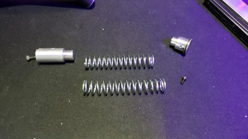
Lever Tension and Lock Mechanism Assembly:
The Lever Tension and Lock Mechanism serves several critical purposes: it applies tension to ensure the lever properly grips the cartridge lever catch, it helps seal the T.R.A.P handle tube from debris, and it provides an essential safety interlock.
Spring Adjustment: The assembly begins by installing the spring. If you find the cartridge catch is not gripping securely, you may slightly stretch the spring to increase resistance to the lever.
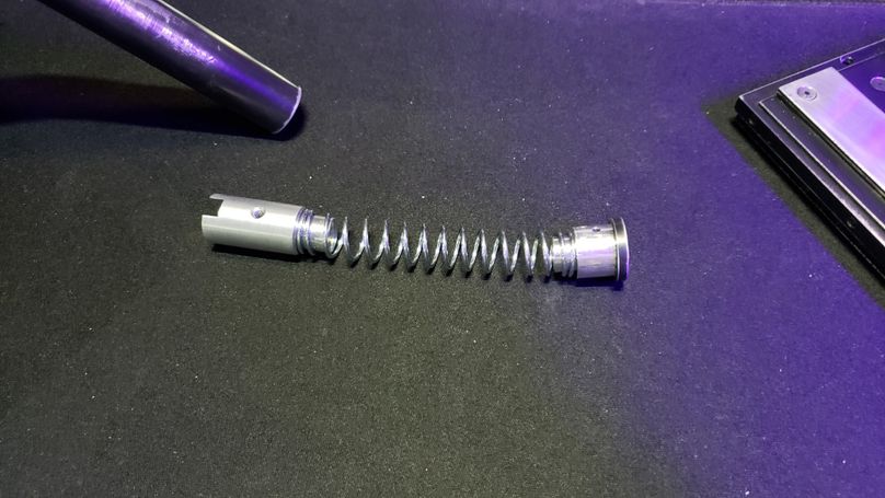
Mechanism Installation: Install the Lock first, followed by the Spring.
Securing the Mechanism: Position the Rear Handle Cap over the mechanism. Secure the Handle Cap using the #4-40 x 1/4” socket cap screw.
Install the lever lock screw Socket Cap #6-32 x 1/4” screw.
CRITICAL SAFETY NOTE: This screw is an important safety mechanism. With this screw in place, you ensure your trap cartridge never accidentally ejects from the T.R.A.P casing. This screw is an addition to meet Federal Oversight Regulations.
Procedure: This screw should only be removed when you are emptying your T.R.A.P into the containment unit.
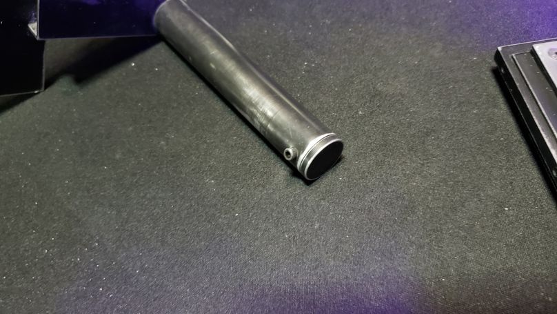
Front Handle Cap Installation:
Cap Installation: Align the Front Handle Cap with the front of the handle tube. The cap is designed to be a tight fit. Use a rubber mallet to gently tap the cover into the handle tube until it is fully seated and flush.
Cap Removal: To remove the Front Handle Cap, you must first uninstall the Lever Tension and Lock Mechanism (Step 2). Once the mechanism is removed, the cap can be gently tapped back off from the rear of the tube.
Handle Cap Maintenance (Note): If, over time, your Front Handle Cap seems loose, there is a groove machined into the Cap designed to resolve this issue. A rubber O-ring can be installed in this groove to restore tension and ensure a secure fit.
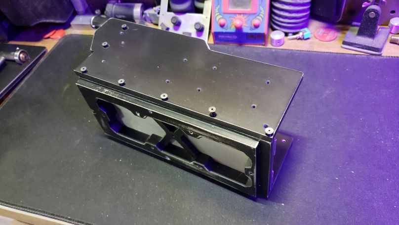
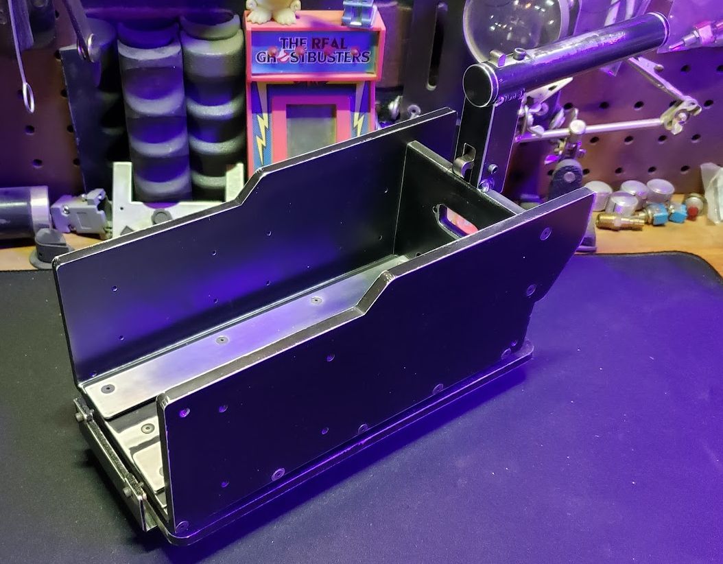
4.4 Assembly of the Walls
This section details the installation of the structural walls, which form the primary structural housing of the T.R.A.P. unit.
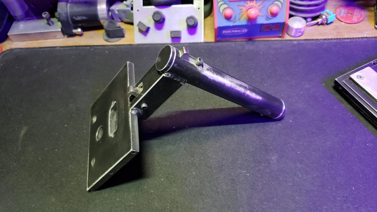
Rear Wall Initial Attachment:
Attach the Rear Wall Assembly to the Chassis Base at the rear U-shaped notch.
Use a #4-40 x 7/16" Socket Cap screw.
Note: Do not fully tighten this screw down yet. This initial looseness allows for proper alignment of the side walls.
Wall Installation:
Position the Left Wall against the side of the Chassis Base and align it with the Rear Wall Assembly.
Secure the Left Wall to the base and rear assembly using 7x #4-40 x 7/17" Flat Head Socket screws.
Repeat the exact procedure for the Right Wall, attaching it to the base and rear assembly using 7x #4-40 x 7/16" Flat Head Socket screws.
Flush Fitting (Important Note):
All Flat Head screws used in the wall assembly must sit flush or slightly below the surface of the walls.
If a Flat Head screw does not sit at least flush, it is recommended to leave the other screws in place and use a countersink bit on the hole to achieve a flush fitting (refer to Section 3.2 for Countersinking procedure)
⚠️ IMPORTANT SAFETY NOTE: Fastener Torque
Due to the small diameter of the #4-40 screws, they are susceptible to snapping under excessive stress. DO NOT OVER TIGHTEN any #4-40 screws during the assembly process. Tighten until hand tight avoid applying significant force. Over-tightening can damage both the fastener and the receiving threads, compromising the structural integrity of the T.R.A.P. chassis.

Final Structural Tightening:
Return to the Rear Wall / Chassis Base screw installed in Step 1 (the 1x #4-40 x 5/8" Socket Cap screw).
Fully tighten this screw to lock the entire chassis structure into square alignment.
4.5 Attaching A T.R.A.P Base
This section details the final assembly step of securing the structural chassis to the mobility base. For this assembly, we are using the traditional Rolling Base (refer to Section 3 for assembly).
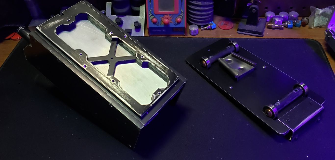
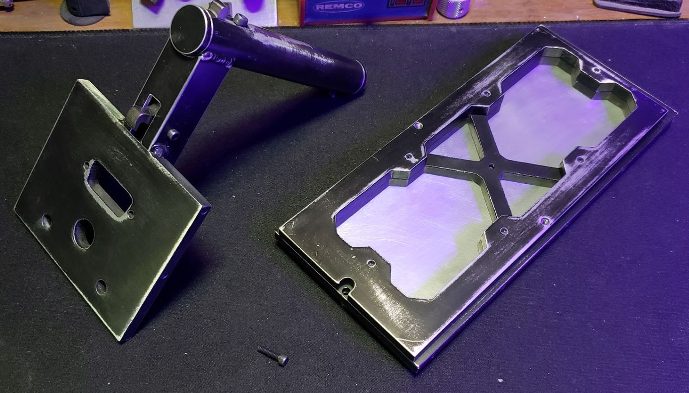
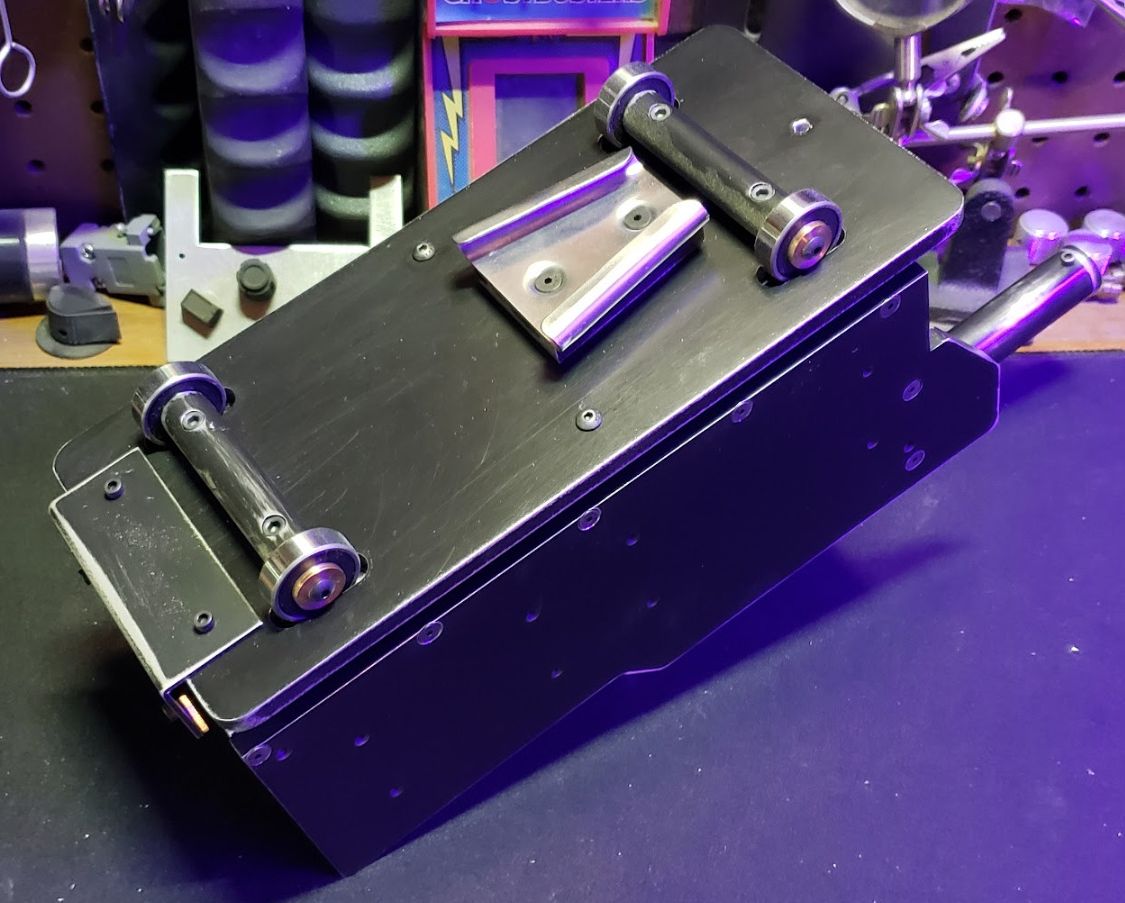
Base Attachment:
Align the assembled Rolling Base with the underside of the T.R.A.P Chassis Base.
Secure the Rolling Base to the chassis using 2x #6-32 x 7/16" Round button cap screws.
Note: Ensure the base is firmly attached before transport or operation.
This concludes the structural assembly of the T.R.A.P. chassis and its Rolling Base. Proper structural integrity is essential to ensure the continued performance and longevity of the entire unit. By ensuring all fasteners are correctly seated, you guarantee a solid foundation for the sensitive internal components