4. Ejection & Control Unit (E.C.U)
Ejection & Control Unit (E.C.U): The Central Hub of the chassis which interacts with the cartridge and houses the trap ejection mechanism.
4.1 Parts List

Before you begin, ensure you have the following components and parts are prepped:
- E.C.U Housing (1x Button Head #6-32 x 7/16”)
- Ejection Mechanism (Ejection Mount, Ejection Cover, 2x Shafts, 2x Springs, 2x Pins, and 4x Button Head #6-32 x 7/16”)
- Label Plate (Blank, Hand Stamped, or Mirror Polished/Lasered)
- E.C.U Front Wall (D-Sub Inner Mount, Adhesive, and 4x Button Head #4-40 x 1/4”)
- Male D-Sub Connector (2x Flat Head #4-40 x 1/2”)
- E.C.U Cover (5x Button Head #4-40 x 1/4”)
- Flat Switch
- Fosters Plug
- Trap Labels
Tool Bits:
- 1/16” hex bit
- 5/64” hex bit
Workshop Field Note:
If you're scanning the reference shots in this manual or looking at my personal T.R.A.P. and spot a typo on the Label Plate or the E.C.U Back Label, don't panic—the crew didn't forget how to spell. Those are just "Easter Eggs" from the original run to remind me to check the work ten times before finishing. Rest assured, I've gone through and caught all those errors for your kit labels, so yours should be good to go.
4.2 ID Label Prep
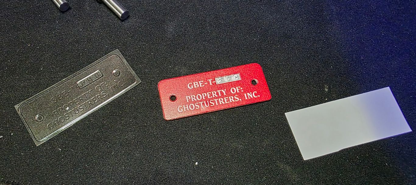
This step involves preparing the Label Plate that sits on the bottom of the E.C.U housing using the provided Epoxy Labels. These labels use a transfer-style application to ensure perfect spacing and a professional finish.
Surface Prep:
- Take the Blank Aluminum Label Plate and ensure the surface is clean. Even a fingerprint can mess with the bond, so give it a quick wipe.
Transfer Prep:
- Carefully peel the backing away so that the label remains attached to the front clear cover. The clear cover is now your carrier and alignment tool.
Application:
- Align the label over the aluminum plate. Once you are satisfied with the positioning, press it down firmly across the entire surface.
Final Reveal:
- Slowly peel away the clear front cover, leaving the epoxy label bonded to the aluminum plate.
Workshop Tip:
If the label tries to lift with the clear cover, stop immediately. Lay it back down, give it another firm rub (a "burnish" in shop-speak), and try peeling from a different corner.
4.3 Ejection Mechanism Install
This section covers the integration of the internal ejection hardware into the main housing.
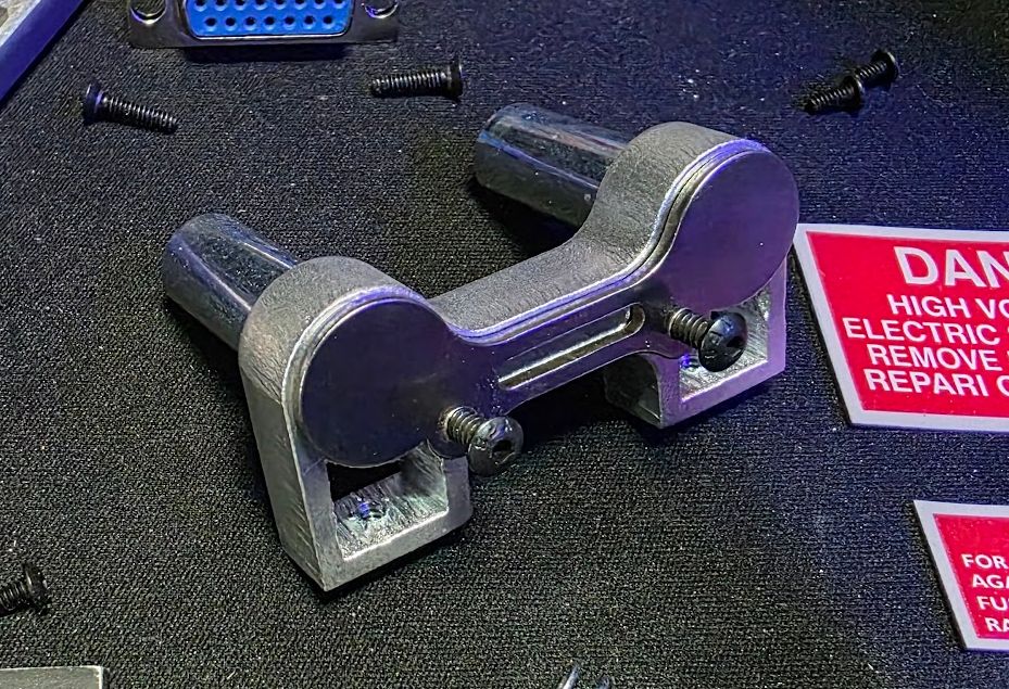
Back Cover Attachment:
- Align the E.C.U Back Cover with the rear of the E.C.U Housing.
- Secure the cover using 2x #6-32 x 7/16” Button Head screws.
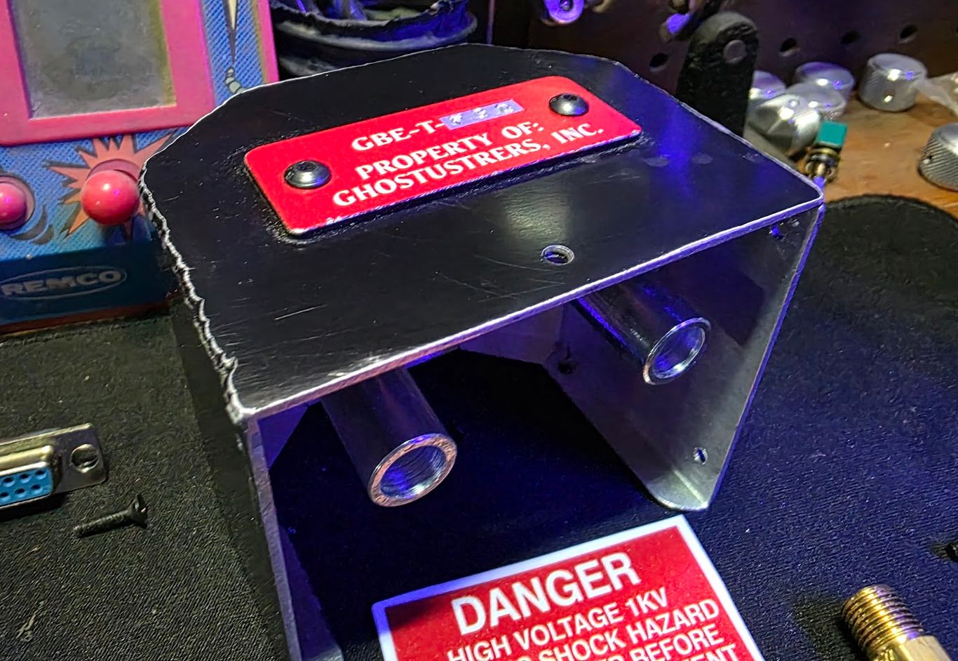
Securing the Ejection Mechanism:
- Position the Ejection Mechanism sub-assembly inside the housing.
- Align your prepped Label Plate on the bottom of the housing.
- Insert 2x #6-32 x 7/16” Button Head screws through the Label Plate and the E.C.U Housing.
Technical Note: These screws pass freely through the clearance holes in the Label Plate and Housing, threading directly into the internal Ejection Mechanism to secure the entire assembly.
IMPORTANT: Epoxy Label Care
If you are using the Epoxy Label, exercise extreme caution when tightening the mounting bolts. DO NOT OVER-TIGHTEN. Excessive torque can cause the epoxy to twist, lift, or chip around the bolt heads, permanently damaging the finish of your label. Tighten only until the assembly is secure.
4.4 Assembly of the Walls
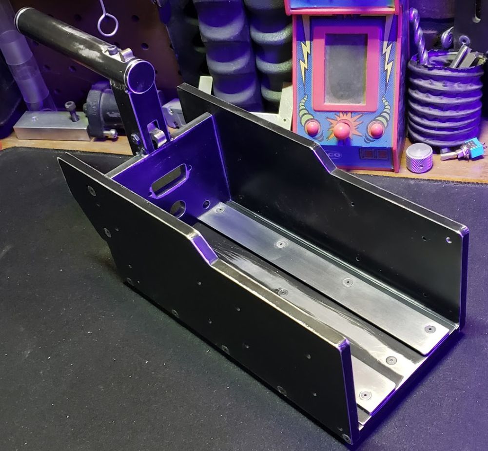
This section details the installation of the structural walls, which form the primary structural housing of the T.R.A.P. unit.
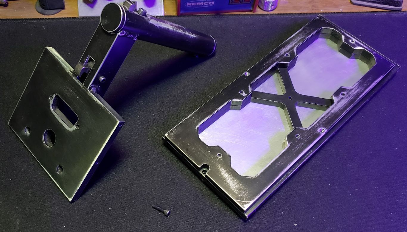
Rear Wall Initial Attachment:
Attach the Rear Wall Assembly to the Chassis Base at the rear U-shaped notch.
Use a #4-40 x 7/16" Socket Cap screw.
Note: Do not fully tighten this screw down yet. This initial looseness allows for proper alignment of the side walls.
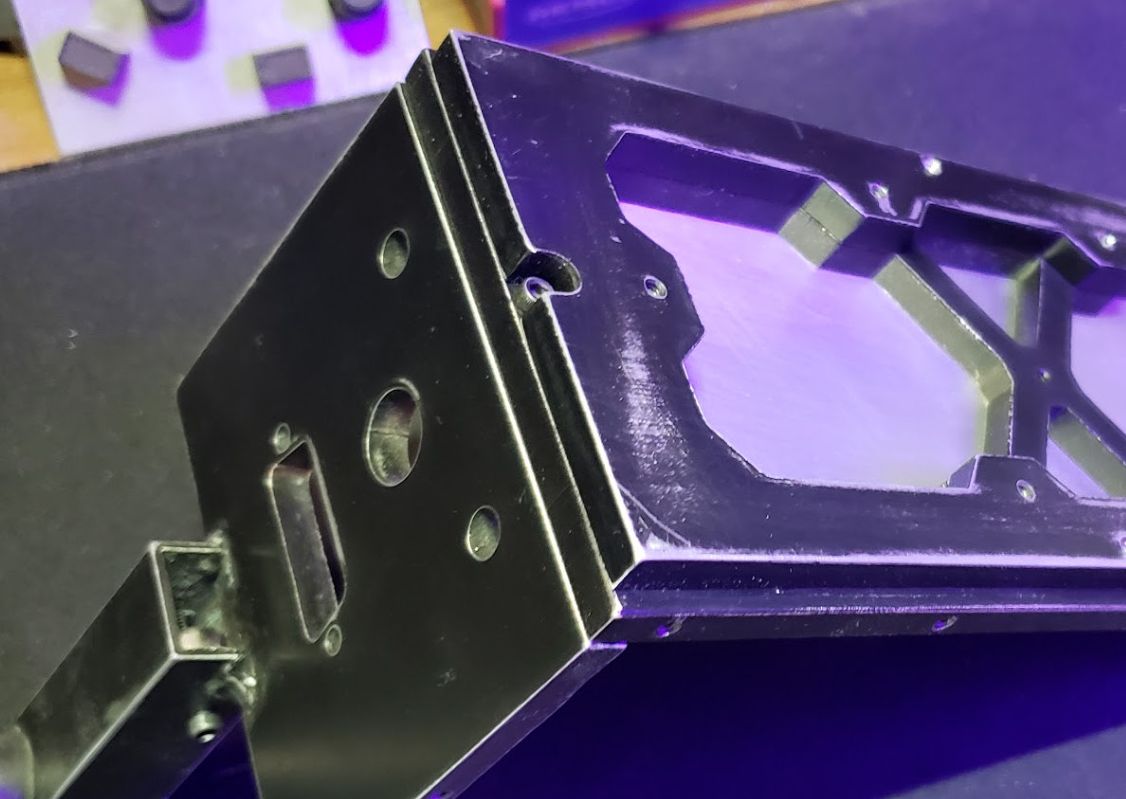
Wall Installation:
Position the Left Wall against the side of the Chassis Base and align it with the Rear Wall Assembly.
Secure the Left Wall to the base and rear assembly using 7x #4-40 x 7/17" Flat Head Socket screws.
Repeat the exact procedure for the Right Wall, attaching it to the base and rear assembly using 7x #4-40 x 7/16" Flat Head Socket screws.
Flush Fitting (Important Note):
All Flat Head screws used in the wall assembly must sit flush or slightly below the surface of the walls.
If a Flat Head screw does not sit at least flush, it is recommended to leave the other screws in place and use a countersink bit on the hole to achieve a flush fitting (refer to Section 3.2 for Countersinking procedure)
⚠️ IMPORTANT SAFETY NOTE: Fastener Torque
Due to the small diameter of the #4-40 screws, they are susceptible to snapping under excessive stress. DO NOT OVER TIGHTEN any #4-40 screws during the assembly process. Tighten until hand tight avoid applying significant force. Over-tightening can damage both the fastener and the receiving threads, compromising the structural integrity of the T.R.A.P. chassis.

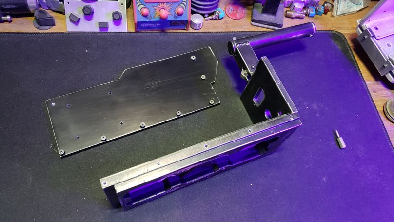
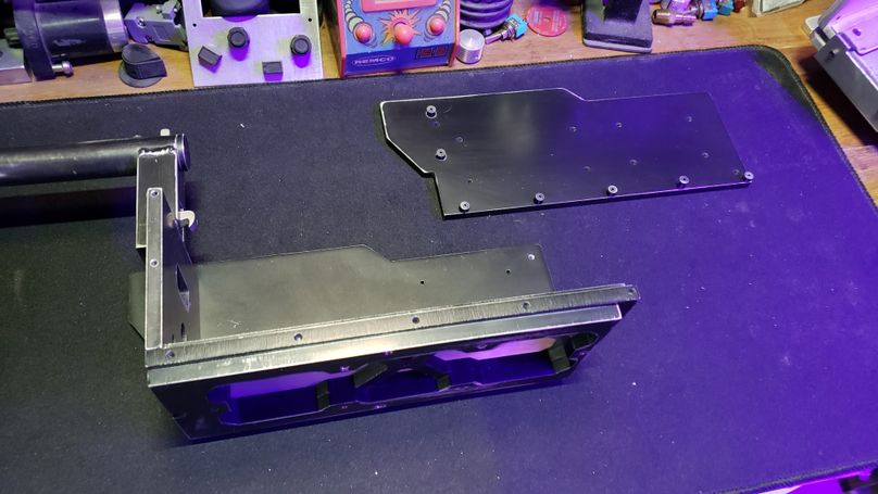
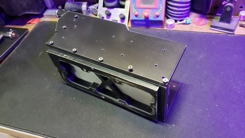
Final Structural Tightening:
Return to the Rear Wall / Chassis Base screw installed in Step 1 (the 1x #4-40 x 5/8" Socket Cap screw).
Fully tighten this screw to lock the entire chassis structure into square alignment.
4.5 Attaching A T.R.A.P Base
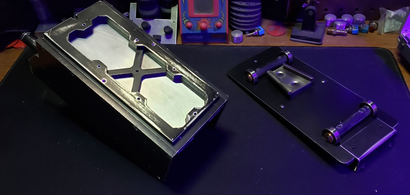
This section details the final assembly step of securing the structural chassis to the mobility base. For this assembly, we are using the traditional Rolling Base (refer to Section 3 for assembly).
Base Attachment:
Align the assembled Rolling Base with the underside of the T.R.A.P Chassis Base.
Secure the Rolling Base to the chassis using 2x #6-32 x 7/16" Round button cap screws.
Note: Ensure the base is firmly attached before transport or operation.
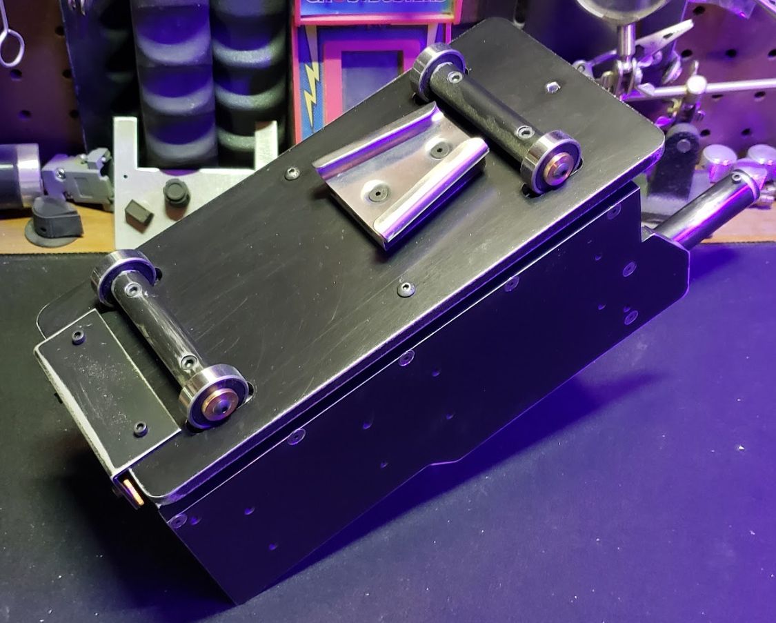
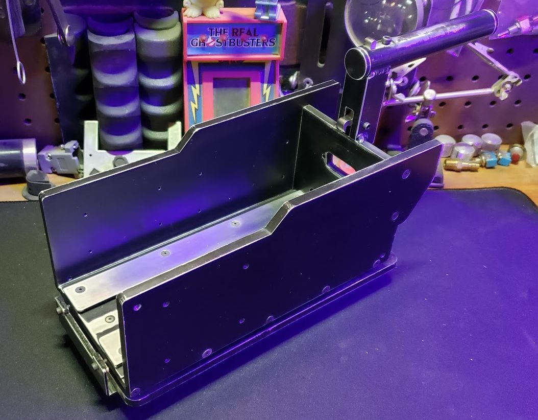
This concludes the structural assembly of the T.R.A.P. chassis and its Rolling Base. Proper structural integrity is essential to ensure the continued performance and longevity of the entire unit. By ensuring all fasteners are correctly seated, you guarantee a solid foundation for the sensitive internal components